")
If you are new to stepper motors read our complete How-To-Guide.
If you want to learn how to make a simple robot, chances are high that you will need to employ the use of motors. There are several different types of motors, but this article will focus on the question “what is a stepper motor”. Choosing the correct type of motor is critical to the success of your robotics project.
If you have heard of a servo motor before, the main difference between a servo vs stepper is that position in a servo is controlled using precise control signals with a 3-phase inverter. On the other hand, position in a stepper motor is controlled using the motor geometry and the position of the coils of its poles.
As a result, a stepper motor typically has a higher pole count. This higher pole count in the stepper allows for more precise motion control as well as higher torque at low speeds. The types of stepping algorithms you choose are also important to getting more torque out of your stepper motor. By using them effectively, you can turn a small unipolar stepper motor into a powerful high-torque stepper motor.
By the end of this article, you will be able to understand one-phase and two-phase stepping as well as drive control signals and truth tables for stepper motors.
In this guide, you will learn about:
1. One-Phase Full Stepping
Before we start using our unipolar stepper motor, we need to cover an important concept so that we can effectively implement it in a project: the stepping algorithms. These algorithms determine how and when each of the electromagnets in a stepper motor will turn on and off in order to allow rotation.
Full stepping is the simplest and most common method of controlling stepper motors.
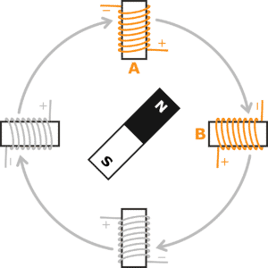
If you’re wondering, “what is an electromagnet” and “how is an electromagnet used in stepper motors”, the image below will help you understand the basic layout of a stepper motor and therefore the answer to these questions.
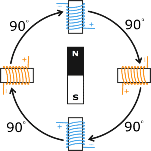
The object in the middle, with the North and South poles, is a permanent magnet. It is typically referred to as the rotor of the machine, and it will rotate as the various electromagnets in the four objects outside of the rotor, collectively called the stator, become active. These four objects are coils that form the electromagnets in the stator. You can see the electrical wiring wrapped around these coils.
As electricity flows through these wires, the electromagnet is able to rotate the permanent magnet towards it.
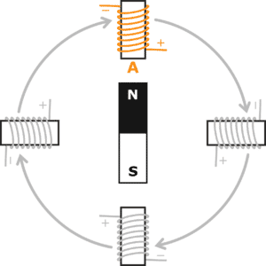
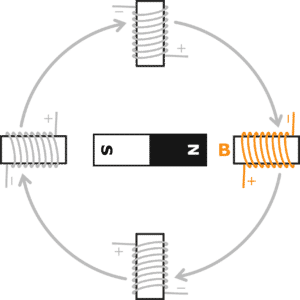
We’ve covered this example in a previous post but we’ll cover it again in more detail here. Let’s first start with the image below which we will call Step 1.
For Step 1, let’s focus on Electromagnet A. We can put current through it to activate this electromagnet. We can see that the North pole of the rotor magnet is attracted to Electromagnet A so that the North pole is pointing upwards towards it. Remember that for magnetic poles, opposites attract so Electromagnet A is actually acting as a South pole magnet.
In Step 2, we deactivate Electromagnet A and turn on Electromagnet B. The permanent magnet turns 90 degrees clockwise to the next position so that the North pole is pointing to Electromagnet B.
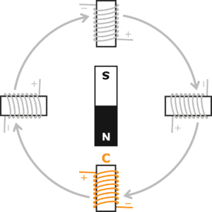
Similarly with Step 3, we turn off the Electromagnet B, turn on the Electromagnet C so that the permanent magnet moves clockwise to this new position.
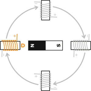
Lastly, in Step 4, we turn off Electromagnet C, turn on Electromagnet D, and the permanent magnet moves from the previous position to the new position. Once you get to Step 4, you repeat this process over again, and that’s how a rotor spins.
2. Two-Phase Full Stepping
One-phase full stepping is a fantastic method for most projects involving a stepper motor. However, sometimes we want to lift a heavier load using the same stepper motor.
We can use two-phase stepping to increase the torque of the motor simply by changing how the electromagnets turn on and off.
Here, we have an example of two-phase full stepping. The two-phase stepping algorithm is very similar to the one-phase stepping but instead of one-phase ON at each step, two phases are ON. You can see this in the image below. Both electromagnets A and B are powered, and the rotor is rotated towards the middle of them.
In two-phase stepping, the step sizes are still the same. The permanent magnet moves 90 degrees from one step to the next. You can see the process for full rotation in the 4 images below.
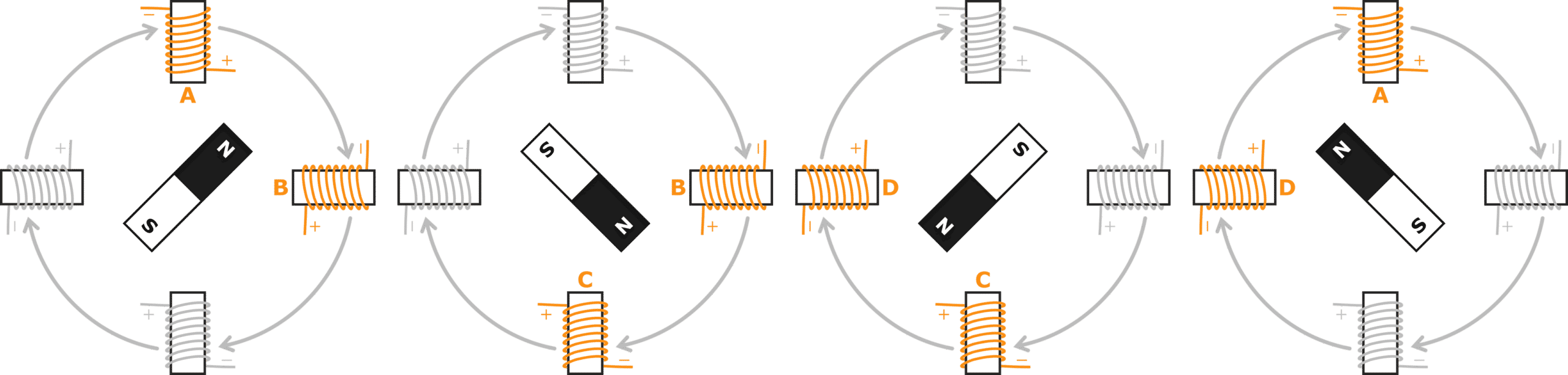
Two-phase full stepping provides roughly 30-40% more torque than one-phase full stepping.
The extra amount of torque can be beneficial to lifting slightly heavier loads with the same stepper motor. That means that we can try two-phase full stepping before buying a bigger or more expensive motor. However, two-phase full stepping has one major disadvantage. It is significantly less efficient than single-phase full stepping. That is because in two-phase, we’re using twice the number of coils at a time, so twice as much electrical power is used.
We use twice the input power to gain roughly 30% additional torque at the output.
If your project requires simple, power-efficient movement, one-phase stepping is recommended. On the other hand, if high torque is needed and electrical power is not a concern, two-phase stepping can be used.

3. Drive Control Signals for Stepper Motors
Signal Diagrams
A basic stepper motor in our example has four coils and four wires to control each coil. The stepper motor wires are typically color-coded to tell you to which coil they are connected. Using these control wires, we can switch the coils on and off for a set amount of time to move the rotor one step. Depending on how we turn the coils on or off, we can change how the stepper motor turns its rotor. For example, in one-phase stepping, the signals will look like this:
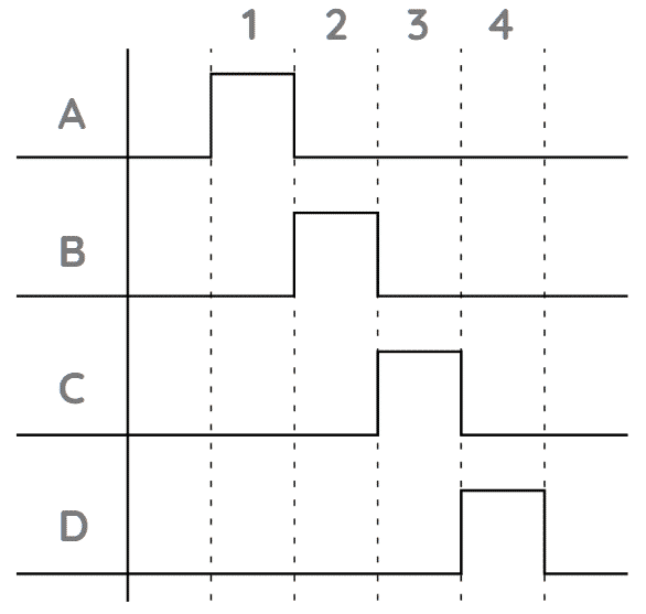
The vertical dashed lines mark the intervals for each unique step of operation.
- In Step 1, a HIGH signal is sent to Phase A so that it’s activated. Phases B, C, and D are sent a LOW signal and are not activated.
- In Step 2, Phase A is set to LOW and Phase B is set to HIGH. The remaining phases stay LOW.
- In Step 3, the same thing happens. Phase B is set to LOW and Phase C is set HIGH.
- In Step 4, Phase C is set LOW and Phase D is set HIGH. We then go back to Step 1 to continue the cycle.
Truth Tables
Let’s put this information into a table so that it is in a written format which will also help us with the next step of stepper control (programming). Use this Truth Table Generator to create your own truth table. A typical truth table format is shown in the image below.
| A | B | C | D | |
|---|---|---|---|---|
|
Step 1 |
|
|
|
|
|
Step 2 |
|
|
|
|
|
Step 3 |
|
|
|
|
|
Step 4 |
|
|
|
|
Using the signal diagram, we can actually construct a truth table. In our truth table, we will write “1” if the signal is HIGH for that phase and “0” if the signal is LOW.
| A | B | C | D | |
|---|---|---|---|---|
|
Step 1 |
1 |
|
|
|
|
Step 2 |
|
|
|
|
|
Step 3 |
|
|
|
|
|
Step 4 |
|
|
|
|
For example in step 1, Phase A is on, and then Phases B, C, and D are off so we will write “1” for Phase A and “0” for the other phases. Fill out the table until all four phases have been completed and we are back at the first step. For one-phase full stepping, the truth table should look like this:
| A | B | C | D | |
|---|---|---|---|---|
|
Step 1 |
1 |
|
|
|
|
Step 2 |
|
1 |
|
|
|
Step 3 |
|
|
1 |
|
|
Step 4 |
|
|
|
1 |
Conclusion
You have now learned the essentials of how to effectively operate a stepper motor and how to achieve greater torque and efficiency to suit the needs of your robotics projects.
Knowledge of how a stepper motor works from drive control signals will give you a strong understanding of when it is appropriate to use a stepper motor instead of another type of motor in your projects. When you later decide to use a stepper motor for your project, knowing the differences between one-phase and two-phase full stepping modes is critical so that you can apply the best and most efficient mode for your needs.
If you need precise position control but want to maximize power efficiency, you can use one-phase full stepping.
Think of an application like an analog clock, where the stepper motor would move the hands in a precise fashion.
If you need precise position control, but also desire more torque, you can leverage the two-phase full stepping mode of operation.
For example, you may want more torque for an application like a robotic arm.
Join our Tech Tribe Community and be the first to learn important global tech news and improve your skills in engineering/robotics/3D printing, and more. Continue to quickly learn all the knowledge you need for DIY electronics or your college program with our Learning Hub.


Comments are closed.