Arduino is a popular open source electronics platform that allows users to create interactive projects using simple hardware and software. If you’re interested in getting started with Arduino tutorials but don’t know where to start then you’re in the right place. This guide will walk you through everything an absolute beginner needs to know about an Arduino microcontroller board before getting started on a first project.
If you are already familiar with the topics we cover in this article and are looking to jump into some beginner Arduino tutorials right away. Here is a summary of the tutorials we recommend for each signal type:
However, if you are not familiar with topics such as AC and DC power, digital signals, analog signals, and PWM signals, then we highly recommend reading through this article first. By going through this guide, you will get much more value out of the above Arduino tutorials by first gaining a solid foundation in the basics. Consequently giving you a head-start in your projects compared to those who glaze over these key concepts
AC Current vs DC Current
Understanding how your Arduino microcontroller gets powered is a great starting point when it comes to understanding the rest of the topics related to getting started with Arduino tutorials.
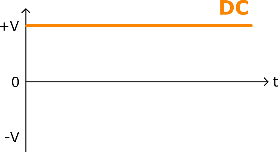
You have probably seen the terms AC and DC before, but might not know what they actually mean. DC stands for Direct Current and AC stands for Alternating Current. Direct Current, as its name suggests, travels directly in only one direction and is capable of providing constant voltage.
The image below shows the voltage plotted against time for DC power as an example. Notice how it forms a straight line and does not change over time. This is the type of power that comes from batteries, and it is used in most of our day-to-day electronics, such as phones and laptops.
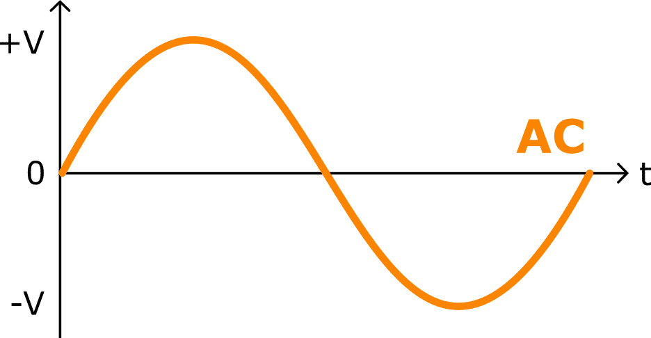
Unlike DC, Alternating Current changes back and forth between two values, just like how day alternates with night.
As an example, we can see that voltage is alternating between a high positive position and a negative position of equal value from the image below. AC power alternates between these values in a sine wave. This is the type of power that gets carried through power lines and into the power outlets in our homes.
In the context of this article, an Arduino board uses DC power to power itself on. This DC power either comes from your computer via a connected USB cable or through an AC to DC power adapted from your power outlet.
Types of signals are another important topic to know before getting started with Arduino tutorials. Signals are a way of transmitting and receiving information and they are what allow electronic devices to communicate with each other.
In the following sections, we will cover the two main types of signals; analog signals vs. digital signals. We will also cover PWM signals which are a category of digital signals that are commonly used. In each section, we will point out what they each are, how they differ from each other, how to use each of these signals on an Arduino, and a recommended Arduino tutorial to get you started.
What is a Digital Signal?
Digital Signals
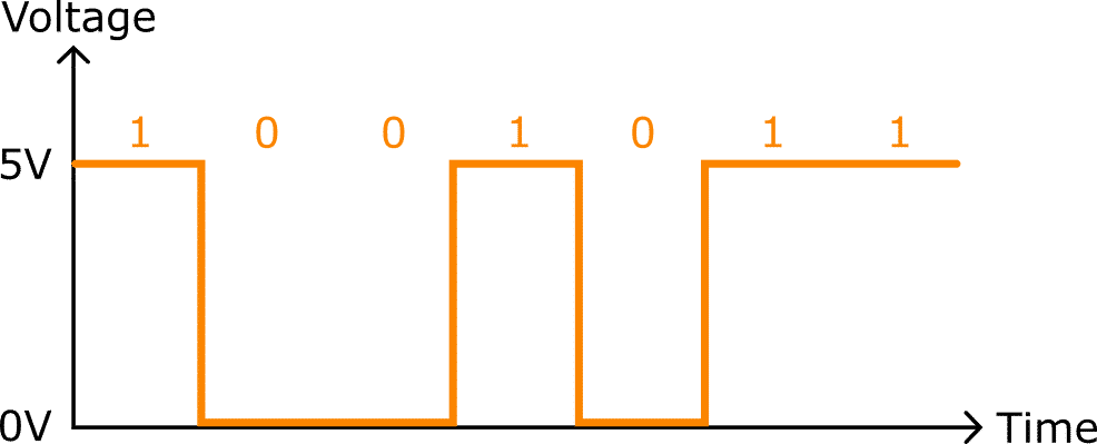
You can imagine a digital signal like a light switch. Similar to a light switch, a digital signal has two states, ON or OFF. In the ON state, the voltage of the signal is equal to the supply voltage. The supply voltage for the Arduino UNO is 5 volts, so if the digital signal is in the ON state, it will have a value of 5 volts. Other terms you will often see instead of ON include HIGH or 1, which all mean the exact same thing. For the OFF state, the voltage is GND (ground) or 0 volts. Sometimes people may call the OFF state LOW or 0.
The image below shows the light-switch-like behavior of a digital signal. When the signal is ON (or 1), it has a value of 5V. When the signal is off (or 0), it has a value of 0V. Notice that there are no values in between, the digital signal can only be 5V or 0V.
What is Digital Communication?
An important application of digital signals is digital communication. Digital communication allows digital devices, such as the Arduino or our computer, to communicate with each other by following a digital communication protocol. You can think of a communication protocol like a language. Both devices need to be speaking the same “language” in order to communicate with each other.
Some common protocols you might hear about include UART (which is how your computer talks with your Arduino via a USB cable), I2C and SPI.
Arduino Tutorials on Digital Signals
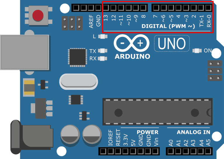
The Arduino UNO has fourteen digital input-output (I/O) pins. These pins are labeled zero to thirteen and can be seen highlighted in the red box in the image below.
A digital output is a signal that starts from the Arduino and goes to another device. You would use the function digitalWrite() in your code to tell the Arduino UNO to send information to another system. On the other hand, a digital input is a signal coming from another device and going to the Arduino UNO. You need to use the digitalRead() function to read this incoming information from other devices. Some of these digital I/O have special functions. For instance, pin 13 is connected to an on-board LED.
For Arduino tutorials on digital signals, we recommend following this blinky example where you will control an LED to turn on and off.
What is an Analog Signal?
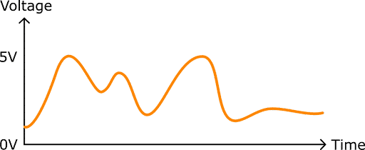
Another type of signal that we use everyday is the analog signal. Define in your mind a dimmable light switch, similar to our light switch analogy for digital signals A dimmable light switch can be completely on or off like a digital switch, but it can also be turned to half brightness, or any value between fully on or fully off. Likewise, an analog signal can be 0 volts, 5 volts, or any value in between, like 2.5 volts, 4.3 volts, or 0.001 volts.
The key difference between analog signals vs. digital signals is thatanalog signals are continuous as opposed to digital signals which are discrete.
What continuous means is that for every point in time, the analog signal has a real value. You can see this in the following image above: the analog signal moves continuously from one value to another over time. There are no “jumps” from one value to another like you saw in the digital signals example.
Arduino Tutorials on Analog Signals
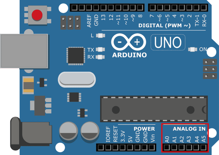
The Arduino UNO has six analog inputs labeled A0 to A5 located at the bottom right corner of the Arduino UNO. These pins are highlighted in the red box in the following image.
Since the Arduino UNO is a digital device, incoming analog signals need to be fed through a device called an analog-to-digital converter (ADC). The ADC converts an analog signal to a digital signal that the microcontroller can understand. The analogRead() function that is built into the Arduino IDE can be used to read values from the specified analog pin. The Arduino UNO does not have any native analog output. In order to have an analog output, there needs to be a device on board called a digital-to-analog converter (DAC), which is just the opposite of an ADC. Since the Arduino UNO does not have a DAC, a PWM signal is often used to simulate an analog signal.
For Arduino tutorials on analog signals, we recommend following this analog input examplewhere you will read an incoming signal from turning a knob.
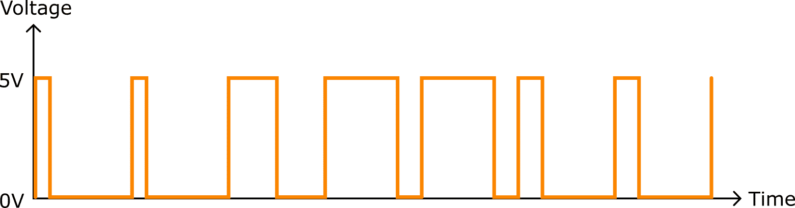
PWM stands for Pulse Width Modulation, and it is often used to imitate analog signals by using digital signals. The name “Pulse width modulation” is just a fancy term for “changing the width of the pulse in this pattern.” The image below shows an example of a PWM signal. You can probably see that the width of the pulse is changing (or modulating) over time.
There are two characteristics used to describe PWM:
Frequency
Duty cycle
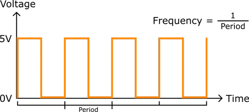
Frequency is the number of times that a pulse pattern happens per second. It is measured in Hertz, which is just 1 over seconds. Mathematically, frequency is the inverse of period, and period is the time it takes for one cycle of this pattern to occur, as shown in the figure below. if you have a frequency of 10Hz, you would have this pulse pattern happening 10 times per second.
The other characteristic of a PWM signal is duty cycle. Duty cycle is the width of the pulse, which is measured in percentage. Duty cycle is basically the amount of space the pulse takes up within the entire period.
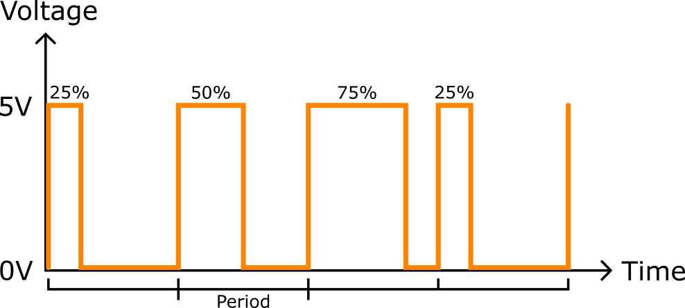
In the image below, you can see the first pulse is 25% of the period, so it’s a 25% duty cycle.
In the second period, the pulse is taking up 50% of the period, meaning that it has a 50% duty cycle.
How Exactly is a PWM Signal Used to Simulate an Analog Signal?
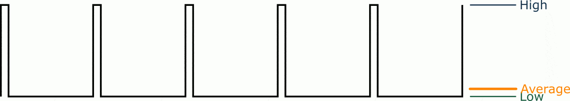
The example below will help answer this question. In the example below, “Low” means 0 volts or ground, and “High” means 5 volts. The orange line that is between the high and low signal is our average voltage. We can see that the frequency (i.e. the time between the rising edges) is constant. However, from the changing widths of the pulses, you can see that the duty cycle (percentage of time that each pulse is high) is changing. As the width of the pulses change, we can see that the average voltage over time is going between ground and 5 volts. The larger the duty cycle, the larger the average voltage.
The varying average voltage in the graph demonstrates one important characteristic of analog signals: the signal can be any value between ON (high) and OFF (low) voltages. This is exactly what we mean by a PWM signal simulating an analog signal.
Arduino Tutorials on PWM Signals
A PWM signal is a type of digital signal, so we still use the same digital pins located on the top of the Arduino. As shown in the image below, here’s a tilde (~) beside certain digital pins: pins 3, 5, 6, 9, 10, and 11. This is to denote that these pins are capable of generating a PWM signal.
The Arduino makes it very easy to generate PWM signals. Use the Arduino analogWrite() function to create an analog output using one of the PWM pins.
The PWM generation from the Arduino does have some limitations that you should be aware of.
One limitation is that the frequency is fixed for the PWM pins. For pins 5 and 6, the frequency is fixed to 980 Hz, meaning there are 980 pulses per second. All other PWM pins are fixed at a 490 Hz frequency, which generate 490 pulses per second.
For Arduino tutorials on PWM signals, we recommend following thisfading PWM examplewhere you will control and LED to fade in and fade out.
Conclusion
You have now learned the most relevant concepts that are key to understanding Arduino tutorials from applications of IoT, robotics, and more! In this guide we covered the following topics:
The key differences between analog signals and digital signals
How to leverage PWM and duty cycle for Arduino
The basics of AC and DC power
These are the key fundamentals that techemployers and colleges wish you knew. With these fundamentals, you’ll be able to complete robotics projects, including those needing digital communication, reading data from sensors, and of course, getting your robots to move!
Join our Tech Tribe Community and be the first to learn important global tech news and improve your skills in engineering/robotics/3D printing, and more. Continue to quickly learn all the knowledge you need for DIY electronics or your college program with our Learning Hub.


")