")
“Stepping motor vs servo motor, what’s the difference and what should I use?”. When it comes to picking a motor for a robotics application, you may find yourself wondering this commonly asked question.
From this article, you will learn what the key differences are between these two motor types, and which one is the best for your robotics project.
Both stepper motors and servo motors are commonly used in the industrial and hobbyist spaces and are a key part of any robotic system.
In the past, a stepper motor was a common choice for a cost-effective and easy-to-use drive motor. However, today a small servo motor or even a high torque servo is readily available and relatively affordable for any engineer or hobbyist as well. Although these two drive motors are often used in similar applications, servo motors and stepper motors are controlled very differently and have their own advantages and disadvantages.
In this guide, we’ll cover everything you need to know about these motor types, including:

How a Stepper Motor Works
The defining attributes of the stepper motor is its ability to move in small incremental steps based on the machine geometry. Because of the way it is designed, one electrical pulse to a stepper motor will turn the rotor one step. Each step moves the rotor a fixed angle amount and the next pulse will move it the same amount. Because of its design, a stepper motor relies on set positions to move the rotor.
To learn more about stepper motors, read our comprehensive beginner’s guide.
How a Servo Motor Works
Servo motors are a very popular type of motor in both the industrial and hobbyist settings. A servo motor’s key characteristic is its ability to control its position which cannot be done with a DC motor alone.
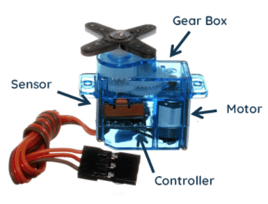
A servo motor is not comprised of just the constructed motor (as a stepper motor is) but a combination of a motor, a positional sensor, and a controller. Servo motors are a great way to implement positional control for many different motor types. As a result, however, it is generally a more complex system to implement as compared to a stepper motor.
The image below details the inner components of a servo motor and each component is explained in more detail in the following sections.
Motor
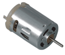
In a servo motor assembly, there is a fully fledged motor which turns the rotor. This motor is typically an AC motor, but in some cases may also be a DC motor. DC motors may be cheaper but are often more bulky. The AC motors used in this application are typically permanent magnet motors, which are more efficient, precise, and smaller, but also more costly. Due to the low cost, however, DC motors are typically used in the hobbyist spaces (such as for Arduino) and AC motors are used where size is typically a concern.
Sensor
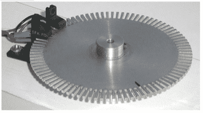
Inside every servo motor is a sensor that is used for position control. This sensor is responsible for determining the angle that the motor has rotated. For many servo motors, an encoder is used to track the rotation of the rotor. Modern position encoders can provide great accuracy for a low cost.
In high-end industrial applications, a resolver can be used as the position sensor.
Some very cost-effective hobbyist servos will use potentiometers to measure the angle of rotation. While you may have used potentiometers in the past as variable resistors, you can also use them as a way to measure the angle. By measuring the resistance of the potentiometer, you can estimate how much the potentiometer has turned. However, most potentiometers cannot turn more than 360°, so this option of position sensing can only be used if the application requires an angle range under this limit.
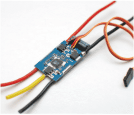
Controller
The controller in a servo motor is a vital component and has two key functions. The controller must interpret the input signal and control the motor based on the sensor feedback.
Because the controller will drive the motor inside the servo, we need a way to communicate the angle that the servo motor should turn to and how fast it should be rotating. There are many ways to do this, but one simple way servos are controlled is by using a Servo PWM. The position sent to the servo motor controller is called the input.
Using the input, the controller of the servo motor must determine both where the output shaft is currently and where the output shaft needs to go. The controller uses data from the sensor to determine the rotor position and reads the input signal to determine what the rotor position should be. Using these two pieces of information, a negative feedback loop is set up, which calculates the difference (also called error) to see if the motor is at the correct position. If not, it will command the motor to move in the direction it needs to go to reduce the error to zero.
What is Position Control and Why is it Important?
Stepper motors and servo motors are often compared because they are both excellent at position control. For a motor, the position refers to the angle of the rotor or output shaft as compared to the stator. Position control allows the motor to turn from the original angular position to a target angular position. A traditional DC motor can be made to control its speed based roughly on the supplied voltage, but its position cannot be accurately controlled. To do that, a controller must be added to it.
A stepper motor or servo motor can control its position but also its velocity and acceleration.
This is extremely useful in robotics, manufacturing, and many automation applications. Learning when to use steppers and when to use servos is crucial for your robotics projects.
Open-loop and Closed-loop Systems
Servo motors are a great example of a closed-loop system, while stepper motors are a great example of an open-loop system. While both of these motors are able to control their rotor positions, the way they achieve this is very different. In this context, a “loop” refers to the negative feedback loop in a control scheme. The control scheme is the way the position and response of the controller is determined.
Open-loop control is the simpler control scheme of the two. In an open loop, the input is converted to an output based on a process or equation. Open-loop control can be used if the output responds to the inputs in a consistent manner every time.
For example, let’s say you have an RC car that is moves at a maximum of 1 m/s and stopped immediately after its control signal was removed. If you wanted to move the RC car forward by 10 m, you could press the forward button for 10 seconds. The controlled variable in this case is the time the car is moved forward, which is used to indirectly control the position of the car. In an optimal environment, the car would be able to move to the correct position of 10 m. However, if the floor was not level or if the RC car was carrying a heavy load, either of which could slow down its maximum speed, holding the button for 10 seconds may not be enough and the car may not travel the full distance. Open-loop systems are a simple and easy solution that can perform tasks in well-defined environments but are unable to guarantee an accurate result if there are variations in the environment.
Closed-loop control systems are more complicated, but are able to reach the output in a more reliable manner. A closed-loop system is able to get feedback from a sensor to tell the controller how close it is to the desired output. By doing this, the controller is able to constantly monitor the system and stop once the task is completed. Using the previous RC car example, a closed-loop system could incorporate a distance sensor in the car. The controller will tell the car to move forward. Once the distance sensor reads 10m, the controller can stop the car. In this is case, the controlled variable is the position of the car itself.
The difference between the two systems is that the open-loop system was reliant on the car to move at a consistent speed to reach the target while the closed loop used a distance sensor to reach the target. Closed-loop systems are much better at controlling the output of the system, but require more complex designs and the use of sensors, controllers, and algorithms to accomplish the task.
We can see two good implementations of these control schemes in the two motor types. The stepper motor uses an open-loop control scheme. Each step is activated by sending an electrical pulse and it is assumed that the step will move the rotor a fixed amount. Stepper motors work great the vast majority of the time. In certain conditions, however, a stepper motor may slip and cause inaccurate results.
Servo motors use a closed-loop control scheme as they have a built-in position sensor to ensure they move until the correct position is reached. While servo motors are great, they are susceptible to errors if the sensor reading is inaccurate, or they can become unstable if the control scheme is not properly configured for the environment.

Detailed Motor Comparison
Overview
Stepper motors are a great choice for low cost, low speed position control. In general, a stepper motor has fewer parts and less complexity than a servo, while still being able to provide reasonably accurate position control. The minimal complexity allows it to have a low cost and makes it great to implement for many simple tasks. Stepper motors are open-loop and therefore don’t require tuning. Lastly, stepper motors have great holding torque, which is used to hold the rotor still against external forces.
Servo motors have some advantages over stepper motors, but also come with a higher price tag. A servo motor can have a higher torque and speed than a stepper motor, which allows it to work with heavier workloads or perform tasks faster. Servo motors also have the ability to vary their torque, allowing them to work with delicate objects and to set motion profiles in order to move quickly or slowly.
Continue reading the following sections for a more detailed look and comparison of the specific aspects of stepper and servo motors.
Torque
Ultimately, the maximum torque produced by a motor will be limited by its size. When they are of similar size, servo motors will generally produce more torque than a stepper motor.
Most servo motors use a gear train which allows them to convert their speed to higher torques in an efficient way. Servo motors can also limit their maximum torque, which is useful in applications that require gentle movement or strict safety requirements. If high torque or variable torque control is important, servo motors are the best choice for you.
Stepper motors do not offer great torque control but have one key advantage over the servo. They have great holding torque which allows them to remain still when turned on against heavier loads, preventing external forces from moving them when not necessary. For example, stepper motors are often used to adjust alignment mechanisms, such as a dial that needs to be turned and then held in place. Stepper motors are a great choice for producing high amounts of torque while working at low speed.
Speed
Speed control is a crucial element in robotics and manufacturing design. Both stepper and servo motors have a wide range of speeds they can operate at.
To increase the speed of a stepper motor, the controller will need to pulse the step-signals at a higher frequency. While the controller is often able to make pulses quickly, the stepper motor will greatly lose its torque as it increases in speed. This is especially true for full-stepping and half-stepping, but slightly less so for micro-stepping. Therefore, we recommend stepper motors for low-speed applications only.
For a servo motor, the speed is dependent on the motor inside. Many servo motors use DC motors, which can provide high speeds and excellent speed control. As a result, servo motors are generally more advantageous for higher speed applications.
Motion control
As discussed previously, one key difference between these two motor types is that stepper motors are open-loop systems while servo motors are closed-loop systems.
While they are more complicated, closed-loop systems are typically preferred as the sensor is able to determine whether a target has been reached, regardless of environmental variables or changes. A servo motor’s controller can also use complex control schemes to change the motion profile of the output. This allows the servo to alter its speed and acceleration parameters as a function of its position.
While this extra complexity gives servo motors greater control and versatility than a stepper motor, creating and tuning the motion profile or control scheme can be a complex and time consuming task. Many servo motors are tuned by the manufacturer, but each application may require additional tuning for optimal performance.
There are many techniques available that engineers use to tune a closed-loop system. Ultimately, however, there isn’t one right answer. The engineer must find the optimal balance between speed (settling time), stability, development time, and complexity of obtaining the tuning parameters.
Cost
In the past, stepper motors were a cheaper alternative due to the cost of the microcontrollers used in servo motors. Although the prices of both motors (used in small applications and with a similar amount of torque) are competitive in modern days, servo motors are still more expensive than stepper motors.
If cost is a big concern, a stepper motor is likely the best way to drive your robotic system.
Failure Modes
A servo motor is a closed-loop system and relies on its sensor to determine if it has reached the right position or not. This means it always reaches its goal unless the sensor provides an incorrect reading. As a result, the number of possible failure modes of a servo motor are significantly higher.
Due to the simplicity of stepper motors, they have fewer failure modes. Stepper motors are open-loop and their drives track the number of pulses that have been sent to the motor. As an example of one failure mode, consider the normal case where one pulse results in one step. However, under large loads or high speed, the stepper motor may miss or skip a step, even though a pulse has been sent. When this happens, it is called slipping.
Efficiency and Cooling
Generally, servo motors are more efficient and run cooler than stepper motors. If your system is running continuously and aggressively, stepper motors will be more likely to overheat than servo motors. Should this event occur with either motor, you might consider turning off the motor and letting it cool before issuing further movement commands.
Hobbyist Steppers and Servos You Can Buy Now
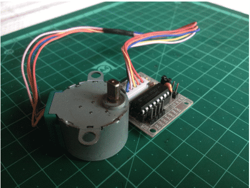
28BYJ-48 Stepper Motor
The 28BYJ-48 is a popular stepper motor used in many hobbyist electronics projects. This little stepper motor provides an excellent opportunity to start learning the fundamentals of stepper motors, stepper drive algorithms, and motion control.
The 28BYJ-48 is often paired with the ULN2003 driver when working with Arduino or other microcontrollers. See the 28BYJ-48 datasheet here.
An image of the motor along with the driver is shown below.
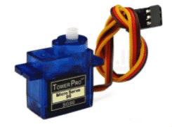
SG90 Servo Motor
The most popular servo motor in the hobbyist space is the SG90 micro servo. These servo motors were originally designed to steer RC cars and planes, but are prolific in the Arduino space.
This low cost and lightweight servo motor has a plastic gearbox and potentiometer position sensor on the output shaft. This 5V servo can be controlled through the servo PWM found in the Arduino Servo library.
For help with setting up libraries in Arduino, check out our Arduino IDE and library setup guide.
Continuous Rotation Servos
The primary objective of the typical servo motor is to provide position control. These motors are quite useful in practice, since most hobbyist servos have a limited range of motion. That means that the typical servos they use can only move a certain number of degrees before they reach their limit.
On the other hand, continuous rotation servos are able to rotate indefinitely and keep a constant speed. They are not a “real” servo in the typical sense as they only provides velocity control and not position control. That makes them similar to an open-loop geared DC motor, but with much better speed control. Because hobbyist servos are so compact and easy to use, continuous rotation servos are a great alternative to using a geared DC motor and H-bridge driver.
Conclusion
From reading this article, you now know the key differences and similarities between servo and stepper motors. From these facts, you no longer have to guess or wonder, but will be able to choose the best type of motor for your robotics projects.
Since every project is different, it’s best to determine what the most important aspect of a project is and then select a motor based on that.
For example, imagine you are building a glowing RGB analog clock. You decide to use a motor to move the clock hands and then, because the clock hands need to move in a precise and timed manner, decide that a stepper motor is best because of its accurate position control.
In another project, say an IoT device that opens and closes window curtains and is controlled from a phone app. A motor could be used to actually control the pulling of the curtains closed or open, and a servo motor may be the best choice because of the higher torque that it can provide.
By understanding the differences between stepper and servo motors, you can better plan the designs for your robotics projects and avoid wasting time and money by selecting the correct motor from the start.

Join our Tech Tribe Community and be the first to learn important global tech news and improve your skills in engineering/robotics/3D printing, and more. Continue to quickly learn all the knowledge you need for DIY electronics or your college program with our Learning Hub.